
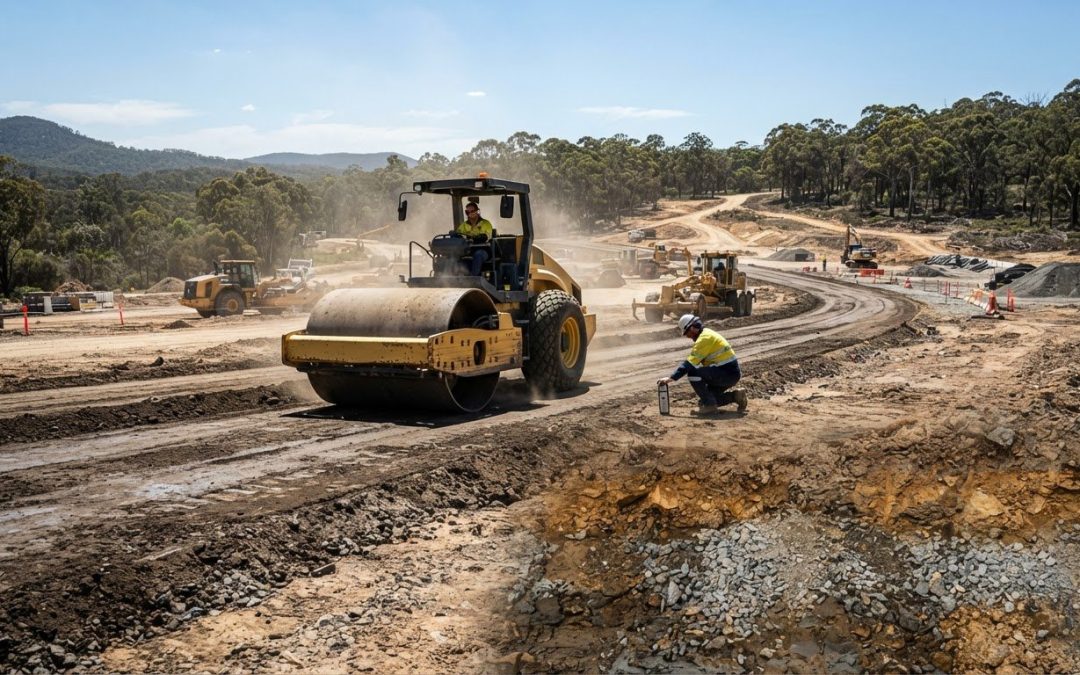
A smooth surface doesn’t prove the ground beneath it is properly compacted. Earthworks compaction methods are assessed by comparing field density and moisture results with laboratory compaction characteristics; in Australia, the Standard Proctor Test is identified with AS 1289.5.1.1, and earthworks specifications commonly target 90 to 98% of maximum dry density, depending on the application. Testing helps show whether the soil is ready to support the next construction layer.
It’s understandable to focus on the roller, but the right earthworks compaction methods depend on the soil, its moisture and the work it must support. This guide explains how compaction testing works, how vibrating and oscillating rollers densify soil, and why settings and passes matter. It also shows how compaction supports roads, foundations, dams and embankments.
Key Takeaways
- Laboratory testing establishes a soil’s maximum dry density and optimum moisture content, helping define a suitable compaction target.
- Roller performance depends on matching drum type, vibration or oscillation settings, and travel speed to the soil.
- Compaction reduces air and water-filled pore spaces, supporting greater soil stability and resistance to traffic and weather.
- Field tests help assess compaction before the next fill layer is placed, supporting quality control through construction.
- Roads, foundations, dams and embankments each call for compaction suited to their materials and intended use; the article also explains where rock pitching fits in site works.
What is Soil Compaction Testing?
Soil compaction testing compares field measurements with laboratory density and moisture results. It helps establish whether placed material has been compacted sufficiently for its intended use.
Moisture and dry-density relationships
A soil’s moisture-density relationship shows how moisture content affects the dry density achievable under a defined compactive effort. The highest dry density on the curve is the maximum dry density; the moisture content at that point is the optimum moisture content.
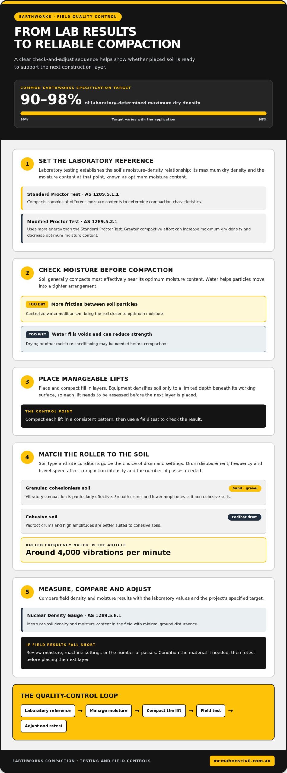
This matters because soil generally compacts most effectively near its optimum moisture content. Water lubricates particles, helping them move into a tighter arrangement; too little water increases friction, while excess water occupies voids and can reduce strength. The Standard Proctor Test, AS 1289.5.1.1, determines these characteristics by compacting samples at different moisture contents. Greater compactive effort can increase maximum dry density and decrease optimum moisture content.
Testing for optimum moisture content
To establish optimum moisture content, laboratory samples are prepared at different moisture levels and compacted to produce a moisture-density curve. The curve identifies the moisture content at which the sample reaches its maximum dry density under the test’s compactive effort.
In Australia, the Modified Proctor Test, AS 1289.5.2.1, determines compaction characteristics using more energy than the Standard Proctor Test. In the field, a Nuclear Density Gauge measures soil density and moisture content with minimal ground disturbance; AS 1289.5.8.1 is identified for this measurement. Comparing field results with laboratory values helps assess whether the placed soil meets its specified target. Earthworks specifications commonly target 90 to 98% of laboratory-determined maximum dry density, depending on the application.
Moisture-related compaction problems
Moisture-related compaction problems occur when soil is too dry or too wet to reach the required density effectively. They matter because poorly compacted material can lack the strength and stability needed beneath construction.
Too little moisture increases friction between soil particles, making them harder for rollers or other equipment to rearrange. Excess moisture fills soil voids, hindering compaction and potentially reducing strength. Either condition can leave field density below the project target, even after repeated equipment passes.
Start by measuring moisture and comparing it with the laboratory optimum before compaction. If the soil is dry, controlled water addition can bring it closer to optimum. If it is wet, drying or other moisture conditioning may be needed. For cohesive soils, compacting near optimum moisture content helps achieve the required maximum dry density. Retest after conditioning to check whether the material is closer to target. Measuring and managing moisture helps reduce the risks of inadequate density and lower soil strength.
Dynamic compaction using vibrating and oscillating rollers
Dynamic compaction uses equipment weight with vibration or oscillation to densify soil. The suitable method depends on soil type, layer depth and the required result.
The main earthworks compaction methods include vibrating and oscillating rollers, impact equipment and static rolling. Each applies energy differently: rollers act repeatedly across the surface, while impact equipment delivers distinct blows.
To compact soil effectively, identify the material and target, place it in manageable lifts, select suitable equipment, then compact and test each layer. If results fall short, adjust moisture, machine settings or the number of passes.
Vibrating and oscillating rollers
Vibrating rollers combine drum weight with rapid vibration; oscillating rollers apply alternating forces through the drum. Both transfer energy into the soil, but in different ways, so the material and site conditions should guide the choice.
Vibratory compaction is particularly effective for granular, cohesionless soils such as sand and gravel. Cohesive soils are better suited to padfoot drums and high amplitudes, while smooth drums and lower amplitudes suit non-cohesive soils. Roller frequency is around 4,000 vibrations per minute. Drum displacement, frequency and travel speed affect compaction intensity and the number of passes needed.
Controlled dynamic compaction
Controlled dynamic compaction uses managed impact energy to densify loose fill, including material on redeveloped industrial sites. A rapid-impact compactor or controlled dynamic compaction unit operates at 10-60 blows per minute, delivering repeated force to the ground.
Unlike a roller travelling over the surface, impact equipment concentrates energy at repeated points. It can address deeper loose deposits, while vibrating or oscillating rollers compact soil placed in lifts. Engineers consider soil composition, treatment depth and measured response when selecting a method. A dynamic cone penetrometer measures resistance as a falling weight drives a cone into the ground, indicating relative compaction.
Soil compaction procedures
A sound compaction procedure links material preparation, equipment settings and field measurements. First identify the soil and the project’s specified density target, then prepare the surface and compare moisture with the laboratory result.
Place and compact fill in lifts because equipment densifies soil only to a limited depth beneath its working surface. Choose a roller suited to the material, then set drum displacement, vibration or oscillation frequency, and travel speed. Compact each lift in a consistent pattern and use a field test to assess the result before placing the next layer.
If field measurements show inadequate compaction, review moisture, lift thickness, soil type and machine settings before continuing. A dynamic cone penetrometer provides another measure of ground resistance, helping engineers assess relative compaction. These checks show whether the method is working or needs adjustment.
For earthworks and concrete works that rely on properly prepared ground, earthworks project support can be a practical next step.
Purpose and benefits of soil compaction
Soil compaction reduces pore space containing air and water, creating a denser, more stable layer. On a road formation, for example, compacted subgrade supports traffic and limits movement beneath the pavement.
That stability matters because loose soil can settle under loads, while water entering the ground can contribute to swelling. Compaction makes soil more resistant to traffic, climate and frost. It also reduces space available for water, helping control changes in soil volume. The required result depends on the material and what the compacted layer must support.
Australian earthworks projects use soil testing and project specifications to determine suitable targets. AS 3798 is identified as the earthworks standard covering lift thickness, compaction equipment and testing frequency. AS 1289.5.1.1 identifies the Standard Proctor Test for determining soil compaction characteristics. These references help connect laboratory results with fieldwork requirements.
Soil type affects how compaction energy works. Cohesive soils, including clay, are fine-grained. Granular, non-cohesive soils include sand, with particle sizes from 0.06 to 2 mm. Padfoot rollers and tamping equipment suit cohesive material, while smooth-drum vibratory rollers work effectively on granular soils.
Typical equipment uses vary with material and access. A rammer delivers 500 to 750 blows per minute and suits confined areas; vibratory plates usually operate at 2,500 to 6,000 vibrations per minute. Rubber-tyred rollers have 7 to 11 pneumatic tyres and weigh 10 to 35 tons, making them suitable for larger compaction areas. These figures describe equipment types, not a universal selection rule.
Compaction time depends on soil, moisture, layer thickness, equipment, site access and testing requirements. More passes may be needed when material or site conditions limit energy transfer. Project costs also depend on these demands, including plant, preparation and testing, and are provided after a quote request.
Match the equipment to the soil and task. Smooth-drum or vibratory plate equipment suits granular material; padfoot rollers and rammers suit cohesive ground. Field measurements help determine whether the specified result has been reached before construction proceeds.
Soil compaction testing and its role in construction
Field compaction tests compare placed soil with laboratory results to determine whether each layer meets its project target. The appropriate test depends on soil composition and the property being assessed.
Field-testing accuracy and soil variability
Soil can vary across a site, affecting how well a field test represents the surrounding area. A result from one location may not reflect a different soil layer nearby.
Temperature, humidity and site conditions can also change moisture content during earthworks. Testing each fill layer before placing the next helps reveal local differences while they are still accessible. Geotechnical assessment connects field observations with laboratory measurements, allowing engineers to interpret density results in the context of the material and its location.
Field compaction testing
Field compaction testing measures in-place density or resistance, then compares the result with the project’s acceptance criteria. A Nuclear Density Gauge measures density and moisture content with minimal ground disturbance, using AS 1289.5.8.1 for field measurement.
The Sand Cone Method measures in-place density by weighing excavated soil and using calibrated sand to determine the hole’s volume; AS 1289.5.3.1 identifies this method. A Dynamic Cone Penetrometer measures resistance as a falling weight drives a cone into the ground, indicating relative compaction. For heavy infrastructure, a plate load test assesses bearing capacity and settlement by measuring movement under loads applied to a steel plate.
Modified Proctor testing
The Modified Proctor Test establishes soil compaction characteristics in a laboratory by applying more compaction energy than the Standard Proctor Test. AS 1289.5.2.1 identifies this test for determining compaction characteristics.
The increased energy comes from a heavier hammer dropped from a greater height. The resulting moisture-density relationship gives the maximum dry density and optimum moisture content for the tested soil under that method. Field density results can then be assessed against the laboratory maximum dry density using the project’s specified percentage. This comparison helps determine whether a layer is ready for the next stage.
Test results serve different construction decisions: density checks assess compaction, while bearing tests examine how ground responds to load. A Clegg impact value can be used to infer CBR through the calculation 0.07 times the impact value squared. This provides an indirect indication, distinct from measuring in-place density.
Soil type and test purpose guide method selection. The Sand Cone Method measures in-place density directly using excavated soil and calibrated sand; a nuclear gauge provides density and moisture readings with less disturbance. A Dynamic Cone Penetrometer indicates relative compaction through penetration resistance, while a plate load test assesses bearing capacity and settlement.
For reliable interpretation, match the field test to the laboratory reference and construction requirement. Where material varies across a road formation or foundation area, testing individual fill layers can reveal changes before they are covered. The results help determine whether work can proceed or needs adjustment.
Compaction applications in roads, foundations, dams and embankments
Compaction supports different construction functions, from road traffic to building loads and water-retaining structures. Typical earthworks specifications target 90 to 98% of laboratory-determined maximum dry density, depending on the application; roads, building pads and trenches do not share one universal target within that range.
For roads, compaction creates a stable formation beneath the pavement and helps granular fill resist movement under traffic. Vibratory rollers suit granular fills in roadworks and embankments because vibration helps rearrange particles into a denser layer. Soil type, moisture condition and design requirements shape the specified result. Field testing checks the compacted material against project criteria before further layers cover it.
Foundations and building pads need ground that can support structural loads with controlled settlement. Compaction improves soil stability by reducing air- and water-filled pore spaces, but the method must suit the soil beneath the foundation. Granular material responds well to vibration, while cohesive soils such as clay generally suit impact or tamping action. Testing and the project specification establish whether the prepared layer reaches its required density.
Trenches create a different working environment because narrow access can restrict equipment size. A vibratory plate or rammer can reach places a large roller cannot. The material placed around services and the available clearance influence equipment selection. Assess each compacted layer against its specified target before placing another, helping reduce the risk of weak zones beneath the finished surface.
Dam cores and landfill liners commonly use cohesive materials, which can be compacted with pad rollers. Embankments may include granular fill, making vibratory rollers suitable for those layers. These examples show why one machine cannot suit every earthwork: particle behaviour, moisture and the purpose of each zone shape the method. Moisture content matters too, because soil compacts less effectively when too dry or too wet.
For roads and embankments, construction sequence matters as much as equipment choice. Fill is placed in lifts because compaction energy reaches only a limited depth beneath the working surface. Testing each lift provides a check before the next one covers it. For heavier infrastructure, a plate load test can assess bearing capacity and settlement by applying loads to a steel plate and measuring the resulting movement.
Australian project specifications determine the required density and testing approach for each application. Council requirements for road embankments may refer to Roads and Maritime Services (RMS) standards. Use the project’s stated target rather than applying the broad 90 to 98% range as a blanket rule. For construction work involving earthworks and concrete, discuss your civil project as a next step.
For roads, building pads and trenches, typical targets fall within 90-98% of laboratory-determined maximum dry density, with the exact requirement set by the project and the conditions of each application.
McMahons Civil and Contracting: Rock Pitching
McMahons Civil and Contracting is a practical next step when your civil project includes earthworks or rock pitching alongside its compaction requirements. Rock pitching can form part of site works where placed rock is required, while Earth Works supports broader ground preparation. For project elements involving structures or surface treatments, Gabion Baskets & Reno Mattress and Concrete may also fit the scope.
If your project needs earthworks or related civil construction, McMahons Civil and Contracting can help deliver the relevant components. Share the site requirements and intended scope to start a practical discussion about the work involved.
To discuss your project, contact McMahons Civil and Contracting or visit mcmahonscivil.com.au.
Plan the next stage of your civil project
Once compaction requirements are clear, align ground preparation with the wider site scope. Consider how access, drainage, retaining needs and the finished surface affect the work sequence, so earthworks support the construction that follows. The right earthworks compaction methods form part of a coordinated project plan, not an isolated equipment choice.
For civil projects involving ground preparation or stabilisation, McMahons Civil and Contracting provides Earth Works, Rock Pitching, and Gabion Baskets & Reno Mattress. These services can connect earthworks with rock placement or retaining structures. Share the project scope and intended outcome to discuss the relevant work.
Contact McMahons Civil and Contracting to discuss your project and take the next step with confidence.
Frequently Asked Questions
How do you choose the right compaction method for different soil types?
Choose equipment by assessing soil composition, particle size, moisture, layer depth and site access. Granular sand or gravel responds well to vibration, while cohesive clay generally needs kneading or impact action. For example, a narrow service trench may restrict roller access, making smaller equipment more practical. Soil classification and the finished layer’s intended use help determine the right combination of equipment and testing.
What moisture content is needed for effective soil compaction?
Effective moisture content is the optimum value established for a particular soil through laboratory testing, not a single figure for every site. A Proctor test produces a moisture-density relationship for the sample and compactive effort used. Compare field moisture with that reference. Soil that is drier or wetter than optimum generally compacts less effectively, so moisture conditioning may be needed to reach the required density.
How is field compaction measured and what tests are used in Australia?
Field compaction is assessed by comparing in-place measurements with laboratory reference values and the project criteria. In Australia, a Nuclear Density Gauge measures density and moisture under AS 1289.5.8.1, while the Sand Cone Method measures in-place density under AS 1289.5.3.1. A Dynamic Cone Penetrometer indicates relative compaction through penetration resistance. The test selected depends on whether the work needs a density reading, a resistance indication or a bearing assessment.
What compaction standards and requirements apply to Australian earthworks?
Australian earthworks requirements are set through the applicable project specification and relevant testing standards. AS 3798 addresses earthworks matters including lift thickness, compaction equipment and testing frequency. AS 1289.5.1.1 covers Standard Proctor compaction characteristics, while AS 1289.5.2.1 covers the Modified Proctor test. The specification establishes the acceptance criteria for the particular work, so road formations, building pads and trench backfill may have different requirements.